

How To Change Turn Signal Relay In 2001 Dodge Neon
I suggest reading this document through entirely before attempting this, there are several variations, options and things you might want to alter. Besides a adept idea to familiarize yourself with the procedure and what it involves beforehand.
Why:
Considering the Neon has inboard mounted plough signals, they are non visible from the side. Typically a manufacturer will mount a 2d light that is visible on the side or make the side markers blink, equally they did on the 9x Neons. However on the North American 2000+ Neons the side markers practise not glimmer and there is no side visible plough bespeak. And so this is really a condom improvement, so that vehicles and pedestrians at right angles to you lot tin can come across your plough signals, as they should.
Goal:
The goal in this case is a simple modification to make the side markers blink in correlation with the turn signal, while maintaining their original operation as parking lights. Also, to brand the procedure as minimally intrusive as possible, reversible and hands repeatable.
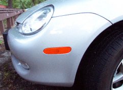
Effigy one - Side Marking
Groundwork:
(this can be skipped if yous exercise not really care to know what is going on)
Beingness that I have a Canadian 2000 Chrysler Neon, information technology comes factory equipped with Daytime Running Lights (DRLs). For the Neon, this means that the front plow signals serve double duty as DRLs and equally a consequence, the only "pure" plow indicate signals are in the dash. (For 2003 the fog lights became the DRLs, not sure if this document applies to those vehicles.) In addition, the vehicle has been wired such that an unpowered, or unconnected lamp or excursion is simply disconnected and not grounded. All the lamps however are switched on the hot side and continuously grounded on the neutral. (Not that a lamp really has an orientation though.) And then why do I care nearly grounding? Well, because if the hot side were grounded when "off", a standard modification used on other vehicles could be used hither. That is, providing the plough signal to the neutral side of the lamp, while maintaining the park indicate to the hot side. But this does not work in this example. Some other option would be to replace the side makers with a dual filament bulb and socket, just I decided confronting that, as it would require more modifications to the car. So thus, I'm left with rewiring the hot side of the side marking lamps to provide the betoken I want.
Basically, I desire to merge the "pure" turn signal with the parking lamp signal. When the parking lamps are off, I want the calorie-free to illuminate directly in relation to the turn signal. When the parking lights are on, I want the light to blink off when the turn signal illuminates. In digital logic, it is an Exclusive OR (XOR) functioning betwixt the ii signals. Being automotive ability signals I want to switch and not digital voltages, digital logic gates are out. Information technology is possible to construct this out of discrete transistors and such, and it would work great, merely the component count and complexity of wiring increases a lot so I decided against this. So, in the end I settled on relays. A relay is an electrically controlled physical switch (or electrically controlled electronic switch in the case of solid state relays).
In relay or ladder logic, every bit it is sometimes called, a SPDT (Single Pole - Double Throw) relay tin perform i of the three bones logic operations, AND, OR and NOT. XOR is formed from its inputs (A,B) as follows: XOR = [A AND (NOT(B))] OR [(Not(A)) AND B]. Breaking that into its simplest components, we would need v relays (2 Not, 2 AND, i OR) to perform this operation. Luckily we tin simplify. An OR operation can be simplified down to simply a connectedness of the 2 inputs directly to the outputs. This works considering of the depression level operation, if either of the inputs is "on" power flows to the output. This is called a wired OR and needs to be "fixed" a bit by calculation diodes to make certain the power flows in the right management and non back to the inputs. Then, down to four relays. A bit of a bound here, but [A AND (Non(B))] can be simplified from two down to a unmarried relay. By using A as the input to the relay and having information technology usually connected to the output, while B, when active, disconnects the output. To understand this, consider the example when B is off. A is directly continued to the output, so when A is on, the output is on, when A is off the output is off. Now when B is on, the output is always off or disconnected. So, the only status when the output is on, is when B is off and A is on, or [A AND (NOT(B))]. This applies to the other office every bit well, [(Non(A)) AND B] becomes one relay with B continued to the input and A connected to the switch or actuator (chosen a coil in a relay). And then, we have simplified the problem down to two relays (and 2 diodes). In the finish, we need a set up of 2 relays for each side, left and right. Note: This can be farther simplified past using a DPDT (Double Pole - Double Throw). By connecting the park/headlamp betoken across the ringlet of the DPDT relay and having both the right and left turn signals enter the relay, we can switch them at the aforementioned time. Thus we can apply two SPDT and 1 DPDT relay. I stuck with 4 SPDT relays as they are easier to obtain. Three diodes should be added, with one across each relay coil, in other words, from ground to each of the 3 system inputs, park, left turn, right plow. This is to prevent EMF from the relay coil affecting the inputs.
Then, getting more than detailed, the inputs to our system are the park betoken, the left and right turn signals, and a ground, which we need for performance of the relay coils. The outputs are a left and right side marker lamp signal. As I said before, the only "pure", untainted by DRL, turn signals are in the dash. (Note: while the DRL tainted signals could be used, information technology adds needless logic to remove the DRL portion of the bespeak, specially since information technology has a parking brake inhibit.) So, those input signals must exist tapped from the dash. Considering of the wiring of the vehicle, the side markers are driven by the same indicate, and in addition, this indicate too powers the front parking lamp in the turn signal lamps. Thus, we need to run a new wire from our relay circuit outputs to drive the lamps. The side markers are obviously mounted up front on the bumper extremities and the hot signal wire for each must exist spliced somewhere from the lamp to the splice betoken which is mounted under the left headlamp. I discovered that the splice bespeak under the headlamp is nearly impossible to go at so I spliced in near the marker lamps. So, the last thing to determine is where to put the relay circuit. Basically two choices, in the dash (interior fuse box), or in the exterior fuse box. The exterior fuse box didn't have enough room and I wasn't sure if the spare relay holders were wired or not, and then I put it in the dash area, there is tons of room there, and the bulk of the signals are there anyway. I decided on standard automotive relays for the performance. They work reliably and are resilient and long lasting. Others, including solid land could be used, simply yous would take to discover relays with the needed properties. Namely, 12V coil drive, high immunity to noise and spikes and voltage swings. Low coil power draw, has to handle at least 2A, etc. The but downside to the standard relays is that they make a clicking noise when switching, makes the flasher a little louder. The circuit, shown below in Effigy 2, switches the relays with every flash of the plough signal. Some more than complex circuits could reduce the switching to once per turn signal usage, it would also add a tiny large of lag to the bespeak turning off and of course, complexity.
Ability draw from the input signals to the circuit is slightly increased from the stock configuration. Boosted power is drawn from the park and turn signals to power the relay coils, a very minimal corporeality, still well within safe limits of the existing fuses. The plow signals have to drive the side marking lamps when the park lights are off though, about 5W each, still within margin on the fuses. Boosted safety and protection could exist added by placing fuses inline with the inputs. Fail over mode is pretty adept though. A failed relay will just mean the parking lamps are stuck in a country or ii and malfunctioning. Worst case is if the diodes brusk out, in which example, no damage will exist done, you'll but become a weird race status in which a turn bespeak may temporarily bulldoze the park indicate on from its off state at the starting time of a plough bespeak pulse. Or if relays and diodes fail, again, no damage, just the end result of malfunctioning side markers. Unfortunately this excursion doesn't add together dead bulb detection for the side markers. The existing expressionless bulb operation for the front and rear bespeak lamps is unaffected. Based on the circuit I've created, the parking lamps blink in sequence with the plough signals when the parking/caput lamps are off and alternatively when the parking/head lamps are on. I don't know if this volition work 2001+'s, non-Canadian Neons, or perhaps even non-Threescore Neons, but I don't run into why they wouldn't be the aforementioned. Let me know your results.
What:
PARTS:
- 4 Relays, must exist 12V and handle at to the lowest degree 2A, SPDT, preferably electro-mechanical automotive grade, solid state should work fine
OR
- Alternate: 2 SPDT relays, 1 DPDT relay (replaces the 2 relays which are actuated by the PH_ON signal)
- Relay sockets or some other means to connect the relays
- seven 1N5408 Diodes, can exist easily be substituted, 1N4007 would work fine, 1N5408 is 1000V and 3A, 1N4007 is 1000V, 2A, but that's overkill, need to be at least 1A though and a decent voltage to prevent damage from any surges
- 4 splice/tap connectors 18-22 gauge
- 2 female/iv male coupler connectors (or the other mode, iv female/2 male) or solder if you prefer
- 35 anxiety of wire, at least xx gauge, preferably multicolored
- Various shrink tubing, I used three and 6 mm in 6" pieces
- 25 feet of wire loom, I used by and large 1/4" and some one/2" for the dash wiring
- Solder
- Cable ties, I used ones 8" long in black, 10 or and then
- Roll of Electric tape
- Double Sided Foam Tape
- Plastic Plugs
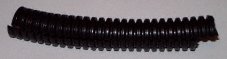
Figure two - Wire Loom
I spent under $100cdn on the parts, and have left overs of most of the stuff.
TOOLS: (not all necessary)
- Cut off pliers
- Wire stripper
- Soldering atomic number 26
- Pilus dryer (for shrink tubing)
- Philips screwdriver
- Torx 25 spiral driver
- Vice grips
- Needle nose pliers
- Stiff metal coat hanger
- Multi-meter/voltmeter /westward continuity checker
- 11mm socket or wrench
How:
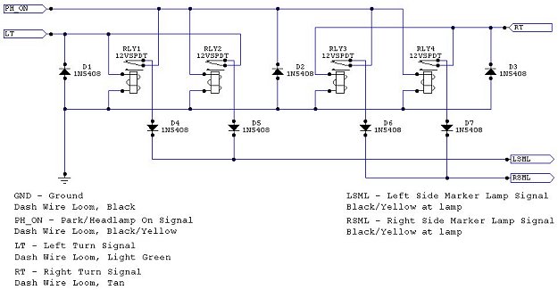
Figure three - Circuit Schematic
The majority of the wiring can exist done beforehand and is much easier to practice at a workbench than inside the automobile. Set the relays aside while working, no use in having them plugged into the sockets while you lot are working.
Begin by gathering and taping the wires together in a dry out run. Also a skilful idea to label the wires. The sockets I used accept a relay with an ISO type plug system and have five color coded wires tailing from them.
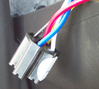
Effigy iv - Relay Socket
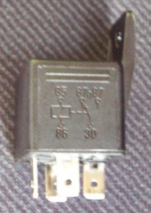
Effigy 5 - Relay
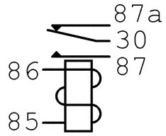
Figure half-dozen - Relay Schematic and Pin-out
First get together all the wires that lead to the "85" connection of the relay, these will exist connected to GND. And then, assemble all pin 87 connections and tape these ends individually with electrical tape and so record them together, these are left unconnected, you can trim them to length so they aren't taking up as well much infinite, but definitely tape the ends, don't want them shorting out. Next get together pin thirty of relay 1, pin 86 of relay ii, pin 30 of relay 3 and pin 86 of relay iv. These will be connected to the PH_ON signal. Gather wires from pivot 86 of relay i and pin xxx of relay ii, these volition be connected to LT. And finally gather pin 86 of relay iii and pivot 30 of relay 4, these connect to RT. Gather pin 87a from relays one and 2, these are the LSML and gather pivot 87a from relays iii and four for RSML. You lot'll also need to find a identify to connect the 3 diodes across the relay coil connections. At the diode socket would be a skilful place, or farther up if its more than convenient to wire.

Figure 7 - Diode Schematic and Pin-out
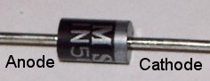
Effigy 8 - Diode
After everything is gathered and in order, begin soldering the LT group which contains the 87a connexion of relay 1 to the anode (the side marked with a stripe is the cathode) of diode ane. Call back to place any compress tubing you lot desire to utilize earlier soldering. Likewise retrieve to make clean the leads of the diodes as they probably take some build upwardly on them and solder volition non stick as well. Strip virtually 1" from the lead and the wire and twist them together, heat the metallic with the soldering fe and apply the solder to the metal non the iron. Repeat the process for each of the other 3 relays and diodes. Identify whatever shrink tubing and then take the cathodes of diodes 1 and 2 and solder them together with a length of wire. This wire will run to the left side marker from the dash, and then brand certain to cutting it to at least 8 feet. Repeat the procedure for diodes 3 and 4 and remember this wire has to run to the right side marker so leave at least xiv feet of wire. It would exist a very good idea to use different wire colors for these two wires to identify them later. I used the convention of blood-red wire for left lamp stuff and black wire for right lamp stuff.
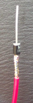
Figure 9 - Diode Connexion to Single Wire
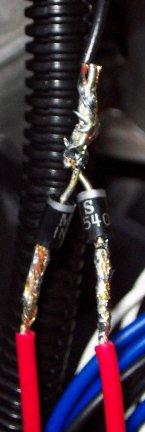
Figure x - Diode Connections and "Wired OR" (Messy Soldering)
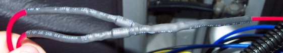
Figure 11 - Shrink Wrapped Diode Connections
Similarly you can complete the connections of the left and right plow signals, the park/headlamp on point and the ground. The grouping of wires you've get together for left turn (LT) is as well continued with a wire which runs dorsum to the dash loom. Right turn (RT) is as well attached to a wire running to the dash loom. In improver the parking/head lamp on (PH_ON) and ground (GND) groups are attached to a wire running dorsum to the nuance loom. Leave about 3 anxiety of these wires.
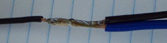
Effigy 12 - Wire Connections
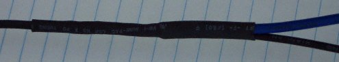
Figure xiii - Compress Wrapped Wire Connections
At this indicate the wiring harness is finished. You should have 4 shorter wires leading from your relay sockets, which are destined for the dash loom and 2 long wires destined for the front side marker lamps. It would exist a skillful idea to exam the harness now. Test continuity of each pin of the relay sockets with the end of the appropriate wire.
Time to caput out to the motorcar with your parcel of wire and tools. Open up the interior fuse box. To the front end of the car within the dash above the fuse box in that location is an opening which leads downwards to the foot well. You want to have the 2 wires that are destined for the left and correct side marker lamps and feed them down through here first.

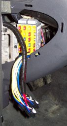
Figure 14 - Fuse Box and Wire Locations
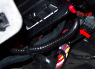
At this point accept a strong metal coat hanger and straighten it out. Tape the two wires to the end of the coat hanger, brand sure they are well secured. You and so want to feed the glaze hanger and wire associates through the existing wire path through the firewall. It's nice to take a friend watching the engine compartment to assist out. The wire path through the firewall is upward backside the nuance on the interior. If you lay on your dorsum in the driver'southward side foot well you should be able to meet a large packet of wires going through the firewall higher up the driver's left human foot remainder, just follow them closely with the coat hanger, its a straight path. Nether the hood, the wires exit the firewall behind the left strut belfry and you'll probably bang your coat hanger into this. You lot'll want to pull the wires through the firewall leaving only enough wire necessary in the dash area. I went to the added problem of estrus shrinking the wires in the location they passed through the firewall as well as taping them up.
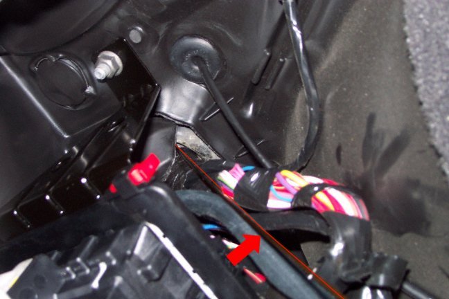
Figure 15 - Lower Firewall with Coat Hanger Indicated
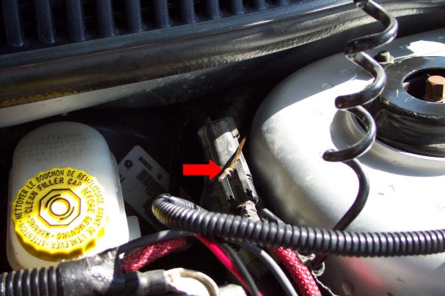
Figure 16 - Upper Firewall with Coat Hanger Indicated
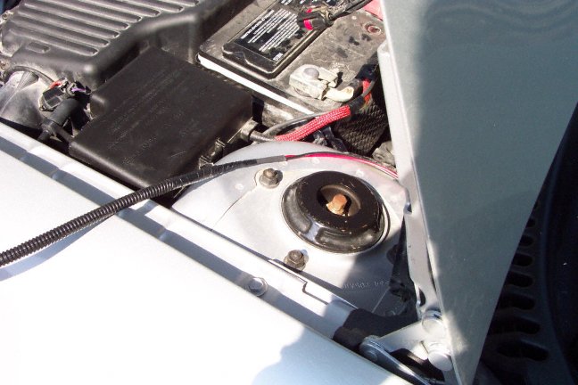
Figure 17 - Upper Firewall Wiring
Now you have a choice. I went basics and followed the original wire loom path exactly. This required removing a bunch of parts. (You might exist able to feed the wire through without removing parts, but be prepared to fish effectually for a while.) It is far easier but to wind these wires effectually the fuse and air boxes. Y'all'll probably desire to install the wire loom before laying the wires. Make sure to secure the wires in key locations, then they don't rub on anything or get caught up, and for general appearance reasons.
Effigy 18 - Piece of cake Nether Hood Wiring Path
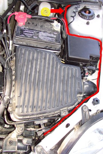
If y'all want to go all out, following the original wire loom is a bit more than trouble. Start past removing the air box cover, remove the air filter, disconnect the throttle body and support information technology, stuff it with a towel to continue dirt out besides. Next loosen the bolts that hold the air box and remove it, probably have to disconnect a sensor. At that place is also a little inflow pipe that has a sensor, both of which you'll probably want to remove. Next unbolt the fuse box. Now you lot should be able to snake your wires nether the fuse box near the chief wire loom.
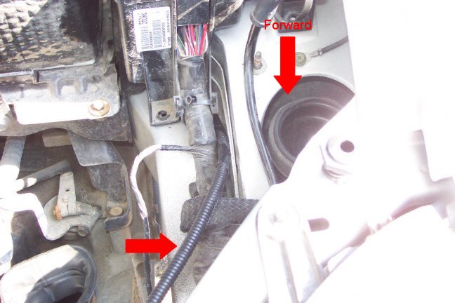
Figure 19 - Fuse Box Wiring with New Wire Loom Indicated
At this betoken, re-secure the fuse box. Then run your wires along the main loom to the left front headlamp area. At this location I separate off the right and left wires and secured the wires. The left lamp wire I ran through a hole in the fender to the lamp area.
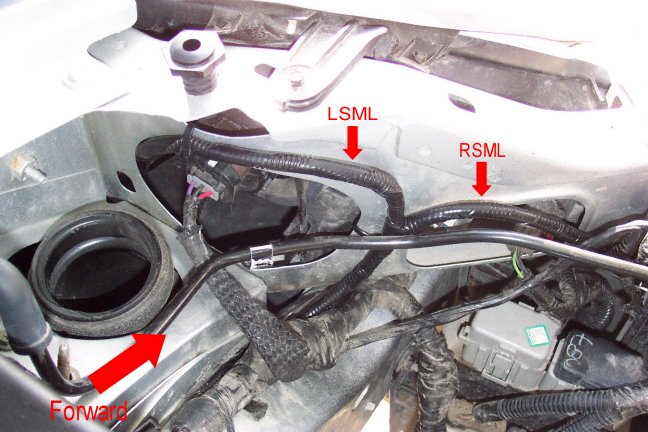
Figure 20 - Left Headlamp Area Wiring with Indicators
The right lamp wire I ran down in front and to the side of the radiator and so across the pan in the forepart bumper, post-obit the fog calorie-free wire loom. I just connected this wire along the bumper expanse and into the fender expanse containing the lamp, securing it at fundamental locations along the style. Re-secure the air box and throttle body at this betoken. I encased all the wires in wire loom and lightly taped it and secured it at various locations.
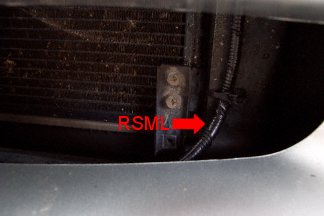
Figure 21 - Left Front Bumper Pan Wiring with Indicator
Back inside the car at present, yous'll need to remove the knee bolster office of the lower nuance. It has two screws on the lowermost point and is clipped at the top simply under the instrument panel. Y'all'll need to unclip the lower surround of the instrument cluster, every bit it clips into the dash piece we are trying to remove. You might besides find information technology helpful to remove the covers on the steering bicycle. These two halves are screwed together with two screws attainable from the bottom front and they are clipped together in the back. Inside the nuance in this surface area at that place is a large wire loom running from the steering wheel downwardly the right side and disappearing into the heart cluster. You'll need to remove the loom and/or tape roofing this bundle to admission the wires.
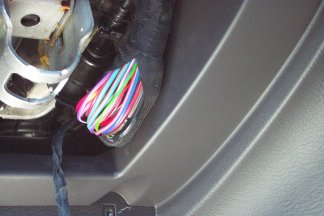
Figure 22 - Nuance Wire Loom
Dorsum to the added wiring hanging from the interior fuse box. The remaining unconnected wires, there should be four, one for the park/headlamp on indicate, one for left and correct turn signals and 1 for ground, need to be fed through the dash towards the wiring loom you've but exposed. Each of the iv wires needs to be spliced into a wire in this loom. I used some splice connectors appropriate for the gauge of wire used. The park/headlamp on wire needs to be spliced to a black wire with a yellow stripe in the bundle. Cutting the wire to length, get out enough room to run the wire without tension, but don't leave likewise much excess every bit yous have to proceed this wire in the dash in the end. Repeat for the left turn bespeak, which connects to a lite green wire. The right turn betoken connects to a tan wire and the ground wire connects to a black wire. Be careful of the blackness wire equally at that place are several in the bundle that are black with various color stripes. The basis wire is pure black.
Effigy 23 - Dangling Wiring from Fuse Box
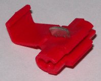
Figure 24 - Splice Connector
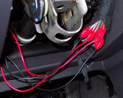
Figure 25 - Spliced Dash Loom
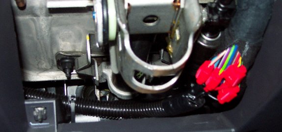
Effigy 26 - Cleaned Upwards Spliced Dash Loom
At this signal it is a skilful fourth dimension to examination everything before cutting any stock wires. First, check the ground connection against an obvious ground near by, an unpainted metal betoken for instance. Check this with a voltmeter, connect one lead to a ground pin in a relay socket and the other to the obvious ground you've located. Turn the car to on and check that they voltage reads near nix. If you lot get something else, check for continuity or that you've spliced into the correct wire. To exam all the other splices, connect the negative lead of your voltmeter to ground and the other lead to the connectedness under test. Test that park indicate has a voltage when either the parking lamps or headlamps are on and most zero voltage when they are off. Note: when running in the on mode without the engine, the voltage should be about 10V, with the vehicle running virtually 12V. The turn signals are a bit trickier depending on the type of voltmeter you have. Make the connections and test that when the turn point is off, a nigh aught reading is indicated. When the plough signals are on, you should see a varying voltage between 10/12V and zip or perchance no reading on a digital voltmeter because information technology cannot lock on to the varying signal. Read your voltmeter transmission to determine its operation. Some other method of testing would be to use a spare lamp to test the signals. Apply some test leads to connect the lamp to the various parts of the excursion you are testing. Although the footing should be tested with a meter.
Add the relays to the assembly now and so exam the outputs of the wires you've pulled to the left and right lamp areas, preferably against the existing ground of the lamp, simply that requires further disassembly, more on this later. Test performance of the left and right turn signals, parking lamps, headlamp and hazard operation and combinations of the above. Verify all existing lamps on your vehicle nevertheless function correctly.
If everything tests correctly you can reassemble the dash. Add any wire loom you'd like and secure the wires. Make certain to secure the wires running through the firewall as they could dangle and get caught in your anxiety while driving. I used some double sided foam record to secure the relay assemblies against the front portion of the dash. You can mount them however you would like.
Effigy 27 - Cleaned Upwardly Interior Firewall Wiring
At present up to the front corners of the car. Note: this a adept time to install clear markers if yous want. Earlier starting, I institute that cranking the wheel hard over to the same side of the car I was working on was very helpful. Y'all'll need to remove the front cycle well linings. These are secured by ii torx 25 screws on the outer fender and two not-reversible plastic plugs on the inboard side. I hate these silly plugs and use diverse combinations of pliers to push and pull them out, deforming them in the process (Yous tin can get new ones from the dealer $2.75cdn each, or from an automotive supply store more like $ii.75cdn a pack). You should then be able to pull the liner back towards the wheel.
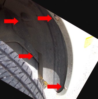
Figure 28 - Wheel Well
You'll demand to remove the reflector assembly for the side marker lamps, this is washed by pulling a clip on the nearest side of the rear of the associates towards the rear of the car. The associates should and then be able to exist pulled out from the outside. The seedling socket tin be removed from the reflector by turning and then pulling. Probably a proficient idea to remove the bulb and set information technology aside somewhere rubber. Ii wires enter the bulb socket, one is solid black, which leads to a basis and will remain intact. The other is black with a xanthous stripe which we will be altering. I found that you lot can't get much slack on these wires, so its a piddling ho-hum to work with. At this point, brand sure your new wire is run to this surface area and has enough of slack available.
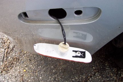
Effigy 29 - Dangling Side Marker Reflector
Annotation: An alternate, less intrusive mode to practise this would be to get a fix of new seedling sockets, and splice into the ground wire of the old one. Squeamish and clean, no cut wires, only tape upwards the erstwhile socket and go out information technology dangling in the bumper well. I think this should be the preferred method. Having a second hazard, I would have washed this.
I cut the existing wire (black with yellowish stripe) in most the center of the slack I had, leaving about three inches of visible slack on each side. I added shrink tube to both sides, stripped about i/4" of the wire and crimped on connectors to both sides. I used female on the lamp side and male on the vehicle, information technology doesn't actually matter which fashion. After crimping, connect the wires and test seedling operation again. It should still function solely as a parking lamp. (Here is the reversible part, just plug the original wires back together to restore original operation. Y'all could also jumper the relay sockets in the dash to restore original operation.) So cut your newly pulled wire to length, strip off 1/four" add together any shrink tubing and crimp a connector on, male in this case. Connect this to the lamp socket and examination performance, it should at present part every bit both a plough signal and parking lamp. Note: based on the circuit I've created, the parking lamps blink in sequence with the turn signals when the parking/head lamps are off and alternatively when the parking/head lamps are on. Check all your other lamps to exist sure they are nevertheless properly functional. If all is successful, tape up all the wires and connectors, brand sure to tape upwardly the spare original connector. Reassemble the reflector and bulb, mountain and finally, reassemble the wheel well liner. Repeat for the other side. I had some trouble getting slack on the right side so I unplugged a couple wires and pulled it out the bottom of the bumper to help.
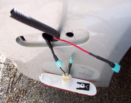
Effigy xxx - Side Marker Wiring
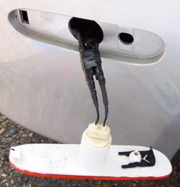
Figure 31 - Cleaned Upward Side Mark Wiring
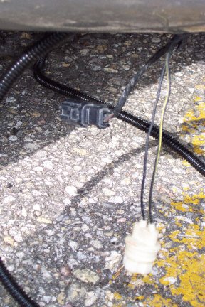
Effigy 32 - Correct Side Marker Wiring
If all went well, you should exist washed now. Equally a final thought, afterward everything is reassembled double check functioning of all lamps in all the diverse settings. Take the motorcar for a brusk examination drive to meet if you observe anything foreign such every bit flickering of interior condition or illumination lamps. Note: the relays are electro-mechanical and so do make some additional dissonance when switching, y'all'll probably find a louder turn signal indicator. But a notation, I didn't take the benefit of this HOWTO when I started, then the actual procedure I used was different than shown here, so some of the pictures might prove something that is out of whack, may have been taken afterward the fact or at a different phase of the process, but they illustrate the bespeak.
The procedure isn't as simple equally I would have liked, only information technology is dictated by the manufactory wiring so this process isn't for the faint of heart. Information technology is repeatable though and easily reversible.
Effigy 33 - Side Marker
Drop me an e-mail with any results if you attempt this. Good luck and safe driving.
Results:
Robert Williams completed the modernistic on his 2001 R/T. He mounted a pair of relays in each fender, tapped the plow signals from the front plow signal lamps (he has no DRL), PH_ON and GND from the existing side mark socket and fed this into a new socket (no cut wires). With DRLs this would work too, just need to run ii wires from the dash for the left/correct turn signals, although you'll want to wrap the relays and connections well, as they are exposed in the fender.
An update, I've been using the modification through a glorious Canadian winter without problems.
March 25, 2002 - I made a change to the schematic to add together protection diodes for dorsum EMF from the relay coils suggested by Tom P and others.
An obvious alternative would be to get a new socket for a dual filament bulb. You could then feed the "low beam" filament from the PH_ON and the "loftier axle" filament from the LT or RT signal. You lot forgo the relays, only have to worry about finding a socket that fits in the reflector and doesn't depict too much power or generate too much heat.
Related Reading Cloth
Source: https://www.ertyu.org/steven_nikkel/bsm.html
Posted by: buttsnessiogs93.blogspot.com
0 Response to "How To Change Turn Signal Relay In 2001 Dodge Neon"
Post a Comment